Simulation eBook - Advanced probing and simulation control
Advanced probing and simulation control
So far, the examples have used two different ways of running the simulations:
- Using the CTRL+J Hotkey as a shortcut to the
Run your simulationdialogue. - Using
spice directivesto run simulations straight from the F8 Hotkey (was CTRL+R) so that, with a few simple key strokes, it is easy to switch between several different simulations from a single simulation schematic.
The following sections will show how to do more advanced signal probing which, when combined with the use of spice directives to control simulations and the flexibility of the
Text type > spice/comment
text attribute to switch between sets of probing and simulation commands, takes simulation to the next level.
The probe command
The section on probing signals showed how to probe voltages and currents in a schematic by adding symbols to the schematic in much the same way real pieces of test equipment such as DVMs and scopes and ammeters can be used to measure voltages and currents in a real circuit.
This section and the associated examples will introduce the '.probe' and .save spice directives to measure voltages and currents in a circuit.
This section reinforces the importance of naming all nets as discussed earlier.
What the probe and .save spice directive does
In LTspice, the '.probe' and .save spice directive do exactly the same jobs:
- Replaces voltage probes;
- Provides an alternative way to probe currents simply by placing a 0V Voltage source anywhere a current is desired to be measured;
- Allows several
.probeor.savestatements to be put into a single schematic and using:
Text Attributes > Text type > comment/spice
provides an easy way to select between probing different sets of measurements by switching the state of probe statements between comment (simple inactive text which is ignored by the simulator) and spice (interpreted by the simulator as active spice directives).
For simplicity in the rest of this document, .probe statements will be referred to and demonstrated but all comments apply equally to .save statements.
The syntax of a .probe directive
- The
.probedirective comprises the keyword ‘.probe’ followed by a space separated list of voltages or currents but not expressions; - All probed signals must be in a single line following the keyword ‘.probe’, with no line breaks;
- There can be any number of
.probestatements active in a simulation schematic; - Voltages can be expressed in the form:
netnameorV(netname), where 'netname' is the name of the net on which the voltage is to be probed; - Currents are expressed in the form: I(V_source_name); where
V_source_nameis the name of the voltage source through which the current to be probed is flowing;
These points are illustrated in the following sections.
Using the '.probe' command to make measurements
The examples, Probing voltages 01, Probing voltages 02] and Probing currents 01 have shown how to probe voltages and currents in a schematic by adding symbols to the schematic in much the same way real pieces of test equipment such as DVMs and scopes and ammeters can be used to measure voltages and currents in a real circuit.
This next example introduces the '.probe' spice directive which can be used to measure voltages and currents.
Probing instantaneous power
Unfortunately in EasyEDA, the '.probe' directive cannot be used to measure power by probing the voltage difference across a device and the current through it and then simply multiplying the two signals together using an expression.
It is however, possible to measure the instantaneous power dissipation in a component by using the pwrmeas probe spice symbol. The power is calculated from the instantaneous voltage across the device multiplied by the instantaneous current through it and is represented as a voltage scaled as 1V/Watt. The output of the probe therefore needs to have a voltage probe attached to it in order to view the voltage representing the power.
Probing resistances
Unfortunately in EasyEDA, the '.probe' directive cannot be used to measure resistance by probing the voltage difference across a device and the current through it and then simply dividing the two signals together using an expression.
It is however, possible to measure the instantaneous resistance in a component by using the resmeas probe spice symbol. The resistance is calculated from the instantaneous voltage across the device divided by the instantaneous current through it and is represented as a voltage scaled as 1V/Ohm. The output of the probe therefore needs to have a voltage probe attached to it in order to view the voltage representing the resistance.
Using F8 (was CTRL+R) to run a simulation directly
This section introduces the idea of placing the simulation directive directly into the schematic. This makes running a simulation even easier because instead of using the:
**CTRL+J > Select simulation type > Run **
type of key sequence to run a simulation, the key sequence simplifies to just:
**F8 **
(was CTRL+R)
Not only does this make running a simulation easier but it also extends the idea - introduced in The 'probe' command - of being able to quickly and easily change the selection of traces to be displayed in WaveForm, to being able to change the actual simulation to be run as well.
Adding the simulation directive directly into the schematic is easy.
All that has to be done is to type the directive as a line of text in the schematic and then do:
**Text Attributes > Text type > spice **
to turn the passive text (blue font) into an active spice directive (black italic font).
Note that one and only one simulation directive can be active for any one simulation run. The example below illustrates how to do this:
Note also that doing F8 without having first placed an active simulation directive in the schematic sheet will automatically place a default .tran simulation directive in the schematic sheet in large text. If this is not removed or rendered inactive by converting it to plain inactive text, before another active simulation directive is manually placed in the schematic sheet then an error message may appear similar to this:
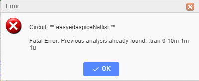
The same type of error message may appear after attempting to run a simulation with more than one active simulation directive in the schematic sheet.