EasyEDA Schematic File Format
EasyEDA Schematic File Format
Note: Schematic, Schematic Symbol, Spice Symbol, Subpart and Subckt are used the same file format. Please check Schematic JSON File Source out before keeping read.
Head
Head information for schematic and subckt.
"head":"1~1.7.5~Author`Dillon`~TRAN`2u`2m`0`{AC`dec``0`0`{DC`0``0`0`{TF```"Format:
- document type :
1 - document version:
1.7.5h - custom attributes: key: value pairs, separate with **, added via **Add Parameter**
- spice simulation configure store, Now can set four types
tran,AC,DC,TF, every type split with{. When opening the simulation dialog, these information will be listed in like below image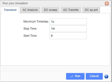
Head information for Schematic Symbol, Spice Symbol and Subpart
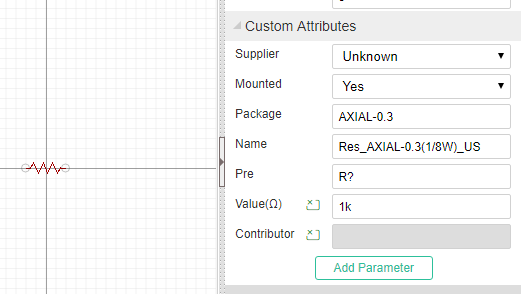
"head":"7~1.7.5~400~300~package`DIP08`nameDisplay`0`nameAlias`Model`Model`555`name`555`pre`U?`spicePre``Contributor`Dillon"Format:
- document type :
7 - document version:
1.7.5 - origin x position. Reserved field, can't be changeded
- origin y position. Reserved field, can't be changeded
- custom attributes: key: value pairs, separate with `, added via Add new parameter.
package: DIP08
nameDispaly: 0 (hide it is name when placed to schematic)
nameAlias: Model
name:555
pre:U? , when place to schematic, will be marked as U1, U2. subpart will be set as `U?.1`, `U?.2` etc.
spicePre:X, `X` stands for a subckt.
sourceId:xxxxxxxxx (just for schematic Lib and spice symbol)Place it to schematic canvas, it's attributes will be looked like below image. The name field is alias as Model and it is invisible.
Canvas
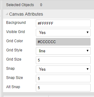
"canvas":"CA~1200~1200~#FFFFFF~yes~#CCCCCC~10~1200~1200~line~10~pixel~5~400~300"Format:
- command: CA
- view box width: 1200, View Box Width / Canvas width = scaleX
- view box height: 1200,View Box Height / Canvas Height = scaleY
- back ground: #FFFFFF
- grid visible: yes/none
- grid color: #CCCCCC
- grid size: 10 pixel
- canvas width: 1200 pixel
- canvas height: 1200 pixel
- grid style: line/dot
- snap size: 10 pixel
- unit: pixel(Always pixel)
- ALT snap size:5 (Snap Size when pressing the
ALTKey) - origin x position
- origin y position
Canvas setting image
Shapes
The shape is an array. EasyEDA store various shape in this field, they are different with a command which locate at the begin of the string.
"shape":[
        "PL~210 100 260 100~#000000~2~0~none~gge58",
        "R~210~110~~~50~30~#000000~1~0~none~gge61",
        "I~90~90~271~105~0~https://easyeda.com/assets/static/images/logo-140x39.png~gge62",
        "PG~310 100 350 130 300 150 290 150 270 120~#000000~2~0~none~gge64",
        "PT~M230 170 C270 200 270 170 240 150 240 150 240 150 240 150~#000000~2~0~none~gge65"
]Rectangle
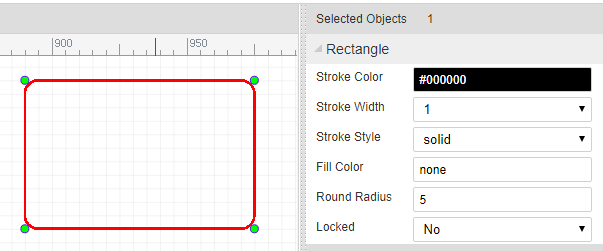
"R~650~0~20~20~230~160~#FF0000~2~1~#9966FF~gge5"Format:
Check Rect element of SVG out.
- command: R
- x: 650
- y: 0
- rx: 20
- ry: 20
- width: 230
- height: 160
- strokeColor: #FF0000
- strokeWidth: 2 //pixel
- strokeStyle: 1
- fillColor: #9966FF
- id: gge36
- locked:null Rect's attributes and image looks like bellow image:
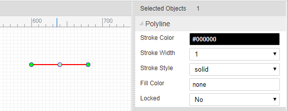
Polyline
"PL~610 130 780 130~#FF0000~5~0~none~gge6"
Format: Check Polyline element of SVG out.
- command: PL
- points: 610 130 780 130
- strokeColor: #FF0000
- strokeWidth: 5 //pixel
- strokeStyle: 0
- fillColor: none
- id: gge6
- locked:null Polyline's attributes and image looks like bellow image:
Path
"PT~M670 300 C830 370 850 230 920 300 920 300 920 300 920 300~#000000~1~0~none~gge17"
Format: Check Path element of SVG out.
- command: PT
- pathString:M670 300 C830 370 850 230 920 300 920 300 920 300 920 300
- strokeColor: #FF0000
- strokeWidth: 5 //pixel
- strokeStyle: 0
- fillColor: none
- id: gge6
- locked:null Path's attributes and image looks like bellow image:
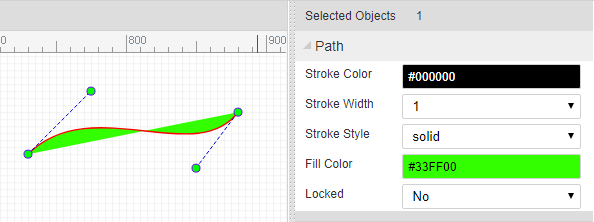
bezier is a path too.
Arc
"A~M 1020 60 A 80 80 0 0 1 953.096 199.904~968.78,121.45,1048.785,201.457,1018.785,61.457,948.785,221.45~#FF0000~3~0~none~gge19"
Format: Arc is a Path element, Check Path element of SVG out.
- command: A
- pathString:M670 300 C830 370 850 230 920 300 920 300 920 300 920 300
- helperDots: the four green dots
- strokeColor: #FF0000
- strokeWidth: 3 //pixel
- strokeStyle: 0
- fillColor: none
- id: gge19
- locked:null
ARC's attributes and image looks like bellow image:
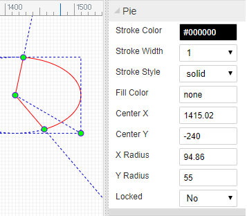
Pie
"PI~M 970 40 L 1189.9 34.4509 A 220 180 0 0 1 923.103 215.863 Z~970,40,1190,220,1327.7106323242188,30.973068237304688,923.1032104492188,215.86282348632812~#FF0000~3~0~#CCCCCC~gge22"
Pie is a Path element, Check Path element of SVG out. Pie is similar with Arc, the pathString has a Z
- command: PI
- pathString:M 970 40 L 1189.9 34.4509 A 220 180 0 0 1 923.103 215.863 Z
- helperDots: the four green dots
- strokeColor: #FF0000
- strokeWidth: 3 //pixel
- strokeStyle: 0
- fillColor: none
- id: gge19
- locked:null
Pie's attributes and image looks like bellow image:
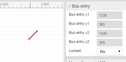
Bus Entry
"BE~0~660~150~670~140~gge15"
Format:
- command: BE
- rotation:0
- start x1: 660
- start y1: 150
- end x1: 670
- end y1: 140
- id: gge15
- locked:null
Bus Entry's attributes and image looks like bellow image:
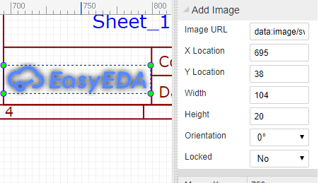
Image
"I~610~10~271~105~0~https://easyeda.com/assets/static/images/logo-140x39.png~gge12"
Format: Check Image element of SVG out.
- command: I
- x: 610
- y: 10
- width: 271
- height: 105
- rotation: 0
- href:https://easyeda.com/assets/static/images/logo-140x39.png
- id: gge12
- locked:null Image's attributes and image looks like bellow image:
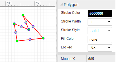
Polygon
"PG~640 10 900 40 920 140 760 230 560 140~#FF0000~2~0~#00FF00~gge10"
Format: Check Polygon element of SVG out.
- command: PG
- points: 640 10 900 40 920 140 760 230 560 140
- strokeColor: #FF0000
- strokeWidth: 2 //pixel
- strokeStyle: 0
- fillColor: #00FF00
- id: gge10
- locked:null Polygon's attributes and image looks like bellow image:
Line
"L~360~160~510~160~#FF0000~2~0~none~gge11"
Format: Check Line element of SVG out.
- command: L
- x1:360
- y1:160
- x2:510
- y2:160
- strokeColor: #FF0000
- strokeWidth: 2 //pixel
- strokeStyle: 0
- fillColor: #00FF00
- id: gge11
- locked:null
Circle
"C~710~170~105~#FF0000~2~0~#0000FF~gge12"
Format: Check Circle element of SVG out.
- command: C
- cx:720
- cy:90
- r:105
- strokeColor: #FF0000
- strokeWidth: 2 //pixel
- strokeStyle: 0
- fillColor: #0000FF
- id: gge12
- locked:null
Bus
"B~570 130 680 130 680 210~#008800~2~0~none~gge19"
Bus is similar with Polyline, Bus is start with B, polyline start with PL.
Pin
"P~show~0~1~670~30~~gge23^^670~30^^M 670 30 h -20~#880000^^1~648~33~0~1~end~~11pt^^1~655~29~0~1~start~~11pt^^0~653~30^^0~M 650 27 L 647 30 L 650 33"
Pin configure
P~show~0~1~670~30~~gge23- command: P
- display: show/'' (bad design, should use yes/none)
- electric: 0, can be ['Undefined', 'Input','Output','I/O','Power']
- spice pin number: 1
- position x: 670
- position y: 30
- rotation: null, can be ['null' or 0, '90', '180', '270']
- id: gge23
- locked: null
pin dot
670~30The gray dot at the end of the Pin, it is important.- pin dot x: 670
- pin dot y: 30
pin path
M 670 30 h -20~#880000- path: M 670 30 h -20, a 20 pixel horizontal line start from pin dot
- pin color: #880000
name
1~648~33~0~1~end~~11pt- visible : 1/0 stand show or hide
- position x: 648
- position y: 33
- rotation: 0
- text: 1
- text anchor: end
- font family: null, default is Verdana
- font size: 11pt, default is 7pt
number
1~655~29~0~1~start~~11ptthe same as name above
dot
0~653~30stands for not. a circle with radius in 3 pixel
- visible : 0/1 hide / show
- circle x: 653
- circle y: 30
clock
0~M 650 27 L 647 30 L 650 33- visible: 0/1 hide / show
- clock path: M 650 27 L 647 30 L 650 33
Pin's attributes and image looks like bellow image: 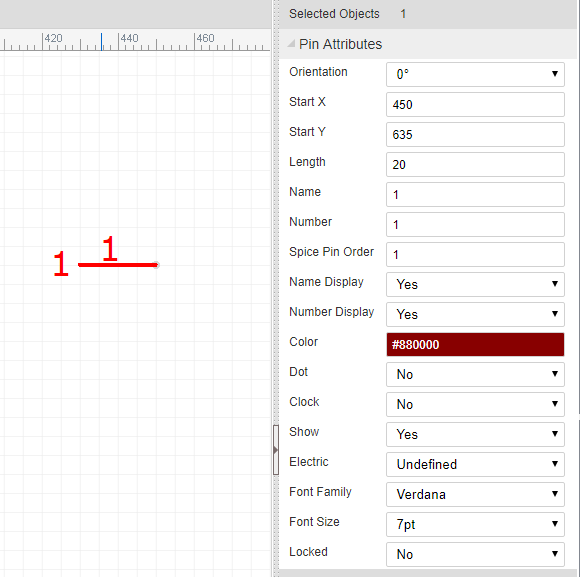
Ellipse
"E~720~90~105~65~#FF0000~2~0~#0000FF~gge12"
Format: Check Ellipse element of SVG out.
- command: E
- cx:720
- cy:90
- rx:105
- ry:65
- strokeColor: #FF0000
- strokeWidth: 2 //pixel
- strokeStyle: 0
- fillColor: #0000FF
- id: gge12
- locked:null
Ellipse's attributes and image looks like bellow image: 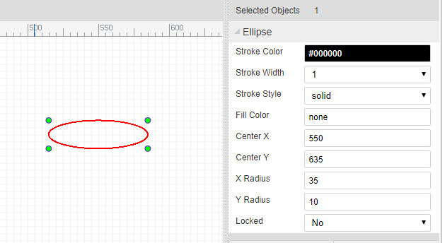
Arrowhead
"AR~part_arrowhead~1060~120~gge23~180~M 1060 120 L 1063 126 L 1055 120 L 1063 114 Z~#FF0000"
Format:
- command: AR
- part Type:part_arrowhead, not used
- x:1060
- y:120
- id:gge23
- rotation: 180
- path String: M 1060 120 L 1063 126 L 1055 120 L 1063 114 Z
- fillColor: #FF0000
- locked:null
Arrow head's attributes and image looks like bellow image:
Annotations
"T~L~540~60~0~#0000FF~~9pt~bold~normal~~comment~Text~1~start~gge26"
Check Text element of SVG out. Format:
- command: T
- mark: L //
L= label,N= Name,P= prefixN,Pare for Symbol - position x:540
- position y:60
- rotation:0
- fill color: #0000FF
- font family: null, default is Verdana
- font size: 9pt
- font-weight: bold
- font style: normal
- dominant baseline: null
- text type: comment // comment or spice command
- string: Text
- visible: 1/0 show/hide (use for mark
NorP) - text anchor: start (start middle end)
- id:gge26
- locked:null
Text's attributes and image looks like bellow image: 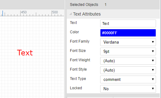
Netlabels
"N~360~100~0~#FF0000~VCC~gge32~start~362~100~Times New Roman~",
Format:
- command: N
- pin dot x: 360
- pin dot y: 100
- rotation: 0
- fill color: #FF0000
- name: VCC
- id: gge32
- text anchor: start (start middle end)
- postion x: 362
- postion y: 100
- font family: Times New Roman
- font size:null default is 7pt
- locked:null
netlabel's attributes and image looks like bellow image: 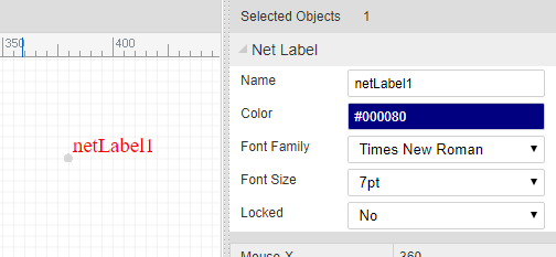
Netflags
Netflag is very similar with netlabel
"F~part_netLabel_gnD~330~110~~gge41^^330~110^^GND~#000080~319~97~0~start~0~Times New Roman~9pt^^PL~330 120 330 110~#000000~1~0~none~gge44^^PL~320 120 339 120~#000000~1~0~none~gge45^^PL~324 122 337 122~#000000~1~0~none~gge46^^PL~326 124 333 124~#000000~1~0~none~gge47^^PL~329 126 331 126~#000000~1~0~none~gge48",
configure
P~show~0~1~670~30~~gge23- command: F
- part id: part_netLabel_gnD
- position x: 330
- position y: 110
- rotation: null [0, 90, 180, 270]
- id: gge41,
- locked: null
pin dot
670~30The gray dot at the end of the Pin, it is important.- pin dot x: 330
- pin dot y: 140
mark string
GND~#000080~319~97~0~start~0~Times New Roman~9pt- net flag string: GND
- color: #000080
- position x: 319
- position y: 97
- rotation: 0 [0, 90, 180, 270]
- text anchor: start (start middle end)
- visible: 1/0 show/hide the net flag string
- font family: Times New Roman
- font size:null default is 7pt
shapes
All other items are shapes.
netflag's attributes and image looks like bellow image: 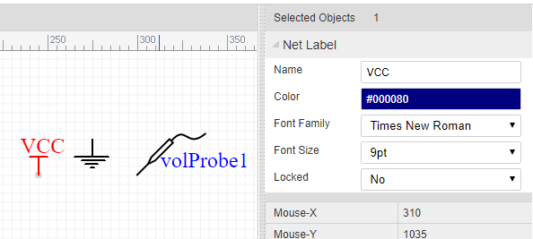
Wire
"W~570 130 680 130 680 210~#008800~2~0~none~gge19"
Wire is similar with Polyline, Wire is start with W, polyline start with PL.
Junctions
"J~420~140~2.5~#CC0000~gge18",
Format:
- command: J
- pin dot x: 420
- pin dot y: 140
- junction circle radius: 2.5 pixel
- fill color: #CC0000
- id: gge18
- locked:null
Junction's attributes and image looks like bellow image: 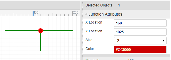
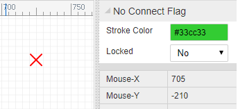
No Connect Flag
"O~960~410~gge5~M956,406 L964,414 M964,406 L956,414~#FF0000"
Format:
- command: O
- pin dot x: 960
- pin dot y: 410
- id: gge5
- pathStr: M956,406 L964,414 M964,406 L956,414
- color: #FF0000
- locked:null
No Connect Flag's attributes and image looks like bellow image:
Symbol
"LIB~220~140~package`C1`nameAlias`Value(F)`Value(F)`1u`spicePre`C`spiceSymbolName`Capacitor`~~0~gge66#@$T~N~214~129~0~#000080~Arial~~~~~comment~1u~1~start~gge68#@$T~P~214~120~0~#000080~Arial~~~~~comment~C1~1~start~gge69#@$PL~218 148 218 132~#A00000~1~0~none~gge70#@$P~show~0~1~200~120~180~gge71^^200~140^^M 210 140 h -10~#800^^0~214~140~0~1~start~~^^0~206~136~0~1~end~~^^^^#@$PL~230 140 222 140~#A00000~1~0~none~gge72#@$PL~222 132 222 148~#A00000~1~0~none~gge73#@$P~show~0~2~210~120~0~gge74^^240~140^^M 230 140 h 10~#800^^0~226~140~0~2~end~~^^0~234~136~0~2~start~~^^^^#@$PL~218 140 210 140~#A00000~1~0~none~gge75"
configure
LIB~270~140~package`DO35-7`nameAlias`Model`Model`1N4001`spicePre`D`spiceSymbolName`Diode`~~0~gge116- command: LIB
- position x: 270
- position y: 140
- rotation: 0, can be ['null' or 0, '90', '180', '270']
- import flag: 0 just used in import from eagle
- id: gge116
- locked: null
shapes
All other items are shapes.
strokeStyle
- 0 : solid
- 1 : dashed
- 2: dotted
Q&A
1. Why don't save the Wire, Annotion, netlabel, netflag to Shape field.
These items will be used to create netlist, save them to separate field will make you spent more less time to do this. We don't need to traversal all the shapes.