Export Pick and Place File
In PCB editor, if you want to generate Pick And Place as a CSV file, you can via:
File > Export Pick and Place File or Top Menu - Fabrication - Pick and Place File. 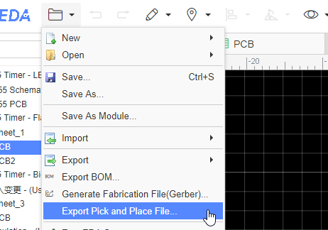
You can set the options: 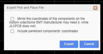
If your PCB has been panelize by the editor, you can enable the "Include panelized components coordinate".
When you open the exported CSV file, you can see: 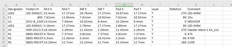
Table description:
- Designator: The component's designator
- Comment: The name of the device, usually the manufacturer's number of the component.
- Footprint: The component's footprint.
- Mid X, Mid Y: The center coordinate of the footprint.
- Ref X, Ref Y: The origin of the footprint.
- Pad X, Pad Y: The first pad coordinates of the footprint.
- Layer: The footprint layer.
- Rotation: The Rotation angle of the footprint.
This file support two units "mm" and "mil", it is following the PCB unit setting.
There is an option "Mirror the coordinates of the components on the bottom side(Some SMT manufacturer may need it, while JLCPCB does not)", you can check with your SMT manufacturer, the mostly SMT manufacturer doesn't need it.
Notice:
In order to support multiple languages, BOM and Pick and Place files (CSV file) are UNICODE encoded and tab-based. If the CSV file cannot be read by your components vendor or PCB manufacturer, please convert the encoding and change the delimiter.
Recommended solution: Save as a new CSV file in Excel or WPS. For example, open a CSV file in Excel, click or select: Save As - Other Formats - CSV (Comma Separated) (*. csv). You can also open the CSV file with any text editor (such as Windows Notepad) and save as ANSI or UTF-8 encoding. If necessary, replace all tabs with commas.