Ratline
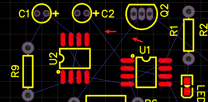
When you layout the track in the PCB, Between Pad and Pad as they have the same net name, a Ratline will be automatically shown among them to reveal that they can be connected with a track.
If you want one ratline do not show on the PCB editor, you can deselect the net in the design manager, as below deselect
+5V: If you still draw a track in+5Vafter deselecting, canvas will not display this track and ratline , but it will show a net text with+5Vas below.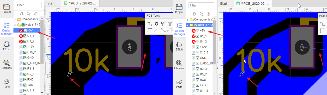 Based on this skill, you don't need to lay GND net before copper area in the PCB.
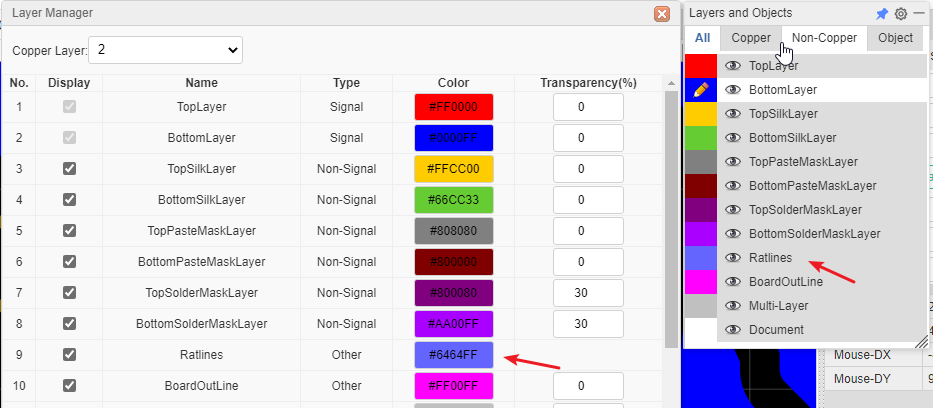
If you want to check the ratlines with highlight, you can click the pencil on the Ratlines Layer as below, and you can change the ratline's color at Layer Manager.
If you want to hightlight one ratline all the time, you can click a pad, press hotkey H, press it again unhighlight.
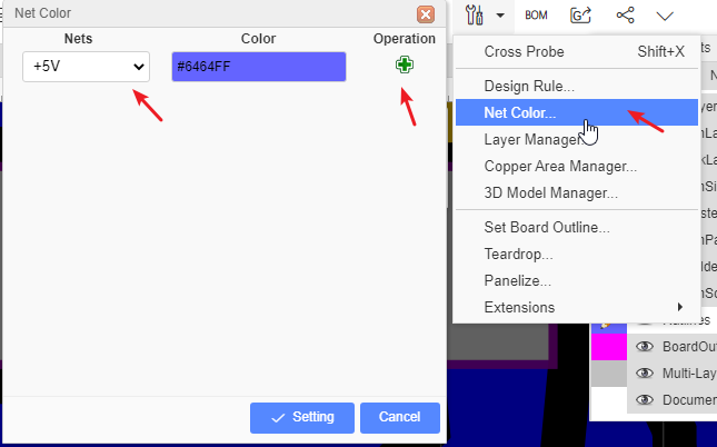
If you want to change one ratline's color, you can set it at: - Tools - Net Color. After setting the color, you need to click the plus icon on the right. The color is not affected by the color of the ratline layer.
If you want to remove one ratline, you just need to remove objects' net. Select it and empty the net.